Description
The octopus program is designed to visualize fields and fibres at the same time. The objects positions to be observed and the fibre configuration can be stored in a results file.
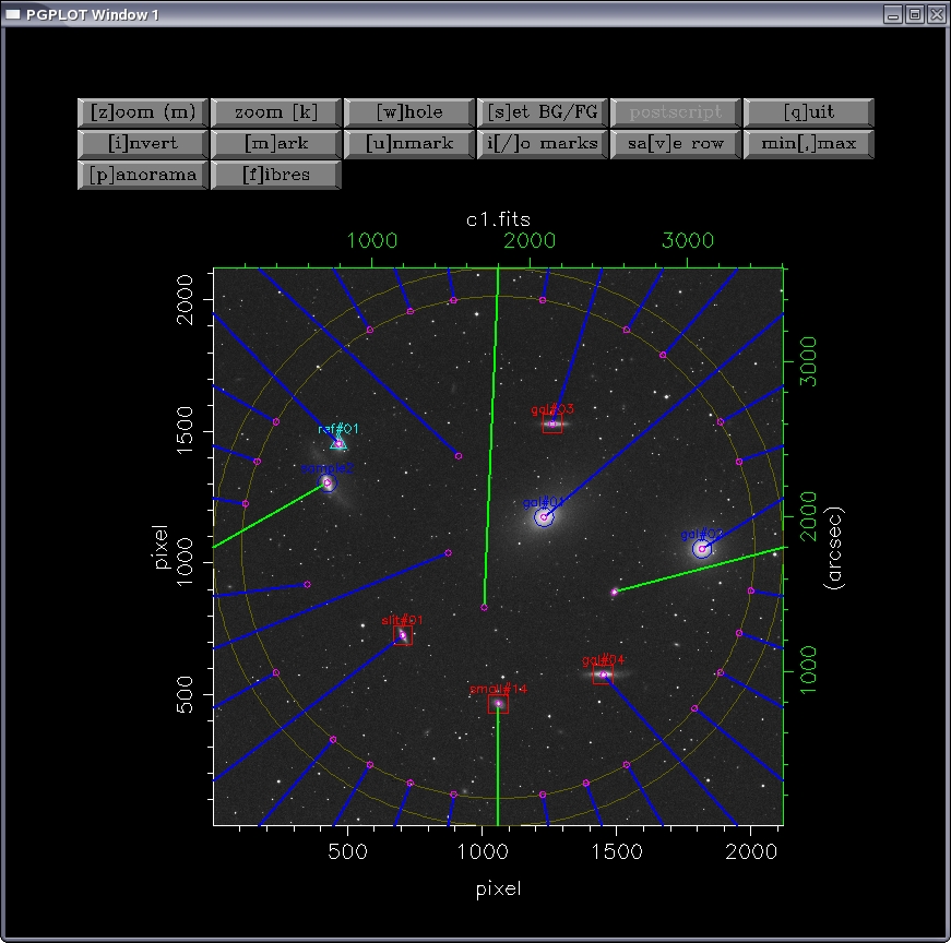
Note that three sample fields (c1.fits, c2.fits and c3.fits) are
provided together with the distributed code.
This is an example showing the execution of the program making use of the first
sample field c1.fits:
$ octopus

**************************************************
Welcome to octopus, the fibre spectrograph
simulator of the UCM Department of Astrophysics
**************************************************

Press <CR> to start...
Input file name? c1.fits
................
printing of fits header
................

OK! File read.
Background: 510.
Foreground: 15832.
> From Scan # 1 to 2119
> From Channel # 1 to 2119
> Total number of pixels: 4490161
> Minimum: 510.
--> in pixel:  1403  151
> Maximum:  15832.
--> in pixel:  216  1506
> Mean : 3445.78638
> Sigma :  1123.87659

octopus has different buttons in the graphic window that let the user perform operations like changing the background or foreground, zooming or file sectioning:
invert Change the gray scale to inverse video
zoom Zoom a given zone with the mouse cursor
mark Put a mark with the cursor
unmark Remove a previous cursor mark
i/o marks Create and read files to store the marks
fibres Enter in the fibre positioning mode
In this fibres mode the user can perform several operations that can be selected in a menu. Let’s see an example where a fibre is selected with the cursor and centred in an object:
(i) Load fibre configuration from file       # Load positions from a file
(s) Save fibre configuration into file       # Save the configuration to a file
(c) Locate fibre to cursor                   # Centre a fibre with the cursor
(p) Park fibre                               # Park a fibre previously positioned
(x) exit                                     # Exit fibre mode

Option  (i/s/c/p/x) ?                        # Choose 'c' for cursor
Select fibre head with mouse ...             # Click on a fibre
OK! Fibre selected is # 35                   # It was fibre number 35
Press mouse button in new fibre location...  # And the object is marked
Updating configuration.......OK!             # Program calculates the positioned
...OK!                                       # And centres the fibre in the marked point
Cursor at 1495.19  970.54  Pixel value: 14692.
(J2000.0) R.A.:  12 29 59.19  DEC.:  +12 20 53.04
(B1950.0) R.A.:  12 27 27.31  DEC.:  +12 37 27.43
Simple exercise
As a simple example to learn how to use octpus let’s follow this exercise. We have a fibre spectrograph that can position the fibres in a 40’-diameter field. We then have 32 fibres for the interesting objects and for the sky background, and another 4 for the guiding stars (fiducial fibres).
We will configure each field taking into account the following restrictions:
At least 10 galaxies from the lists (
list1,list2,list3) should be pointed at.The 4 fiducial fibres (in green colour in the octopus window) will be always positioned centred in the field stars.
Four fibres should be centred in object-free zones to register the sky background. They should be evenly distributed in the field.
The fibres cannot intersect due to design mechanical problems. If two o more fibres intersect, the program shows them in red colour and warns about the existence of a configuration problem. In this case, the conflicting fibre must be parked and another configuration should be used.
At the end, a file will be saved with the results for each field.
Usage tips
The coordinates of an image area can be obtained positioning the mouse in this place and pressing the Tab key. Then octopus will show, in the alphanumeric window, the position in equatorial coordinates and for the B1950 an J2000 equinoxes. This system is very useful to locate one particular object.
The fibres that must be chosen are those closest to the object. In addition, the already positioned fibres must not be largely deviated from their radial orientation. This way the intersection and the conflicts can be avoided.
To position the fibres in the objects, option (c) should be used in the fibres mode with the full image (whole). This simplifies the fibres selection and positioning. Finally, the pointing is refined zoomimg the area of interest with zoom(m) and using again option (c) in the fibres mode.
Fibres are placed with the mouse but they can be used also with the keyboard arrows for a more precise pointing.